From simulation plots to measured controller behavior
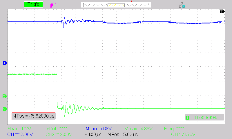
The real-time-control card collects the figures where an algorithm becomes a measured or deployable control response. The SiC converter oscilloscope trace, EV hardware-in-the-loop acceleration profile, pure-droop performance matrix, and pseudo-centralized voltage-current response all show different layers of validation.
The theme is the movement from model to signal. In PV conversion, the trained MPPT decision is checked through converter output and switching behavior. In the EV study, the torque-control strategy is evaluated through a laboratory HIL drivetrain arrangement. In the storage-control work, duty-cycle, PWM, PID, carrier, gate-pulse, voltage, and current responses demonstrate whether the control logic can regulate practical hardware-facing variables.
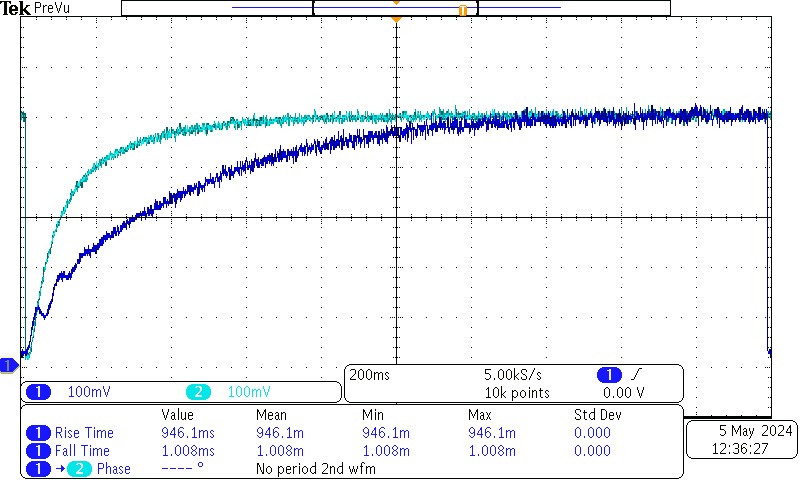
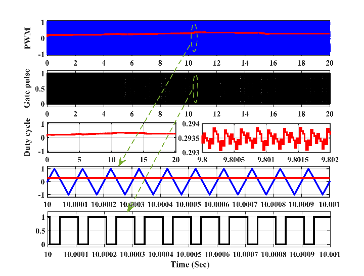
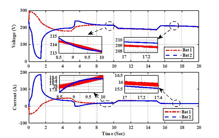
This page is especially useful for students, PhD scholars, and consultancy clients because it shows the discipline behind validation. Real-time work requires sampling awareness, sensing, ADC/PWM synchronization, controller deployment, signal interpretation, and careful comparison between simulated and measured responses. The visuals make that pathway clear without adding unrelated imagery.
- Simulation-to-hardware mapping
- Closed-loop controller testing
- Real-time data logging